-
Working Hours: (00:00 - 24:00)
24/7 Service -
Email:
1029975446@qq.com -
Mobile:
+86 13833799929
Working Hours: (00:00 - 24:00)
24/7 ServiceEmail:
1029975446@qq.comMobile:
+86 13833799929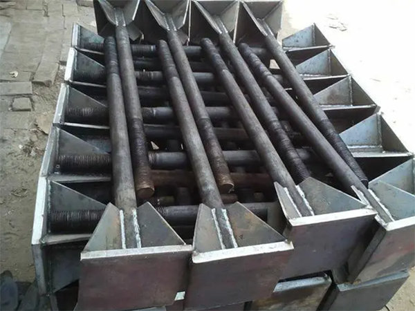
Definition and core structure of welding plate anchor bolts
Welding plate anchor bolts are pre embedded fasteners that enhance the strength of the connection between the bolt and the concrete foundation by welding a metal anchor plate (steel plate) at the end of the bolt. Its core structure is:
Bolt body: usually made of Q345B low-alloy steel or 45 # steel, the surface can be hot-dip galvanized for corrosion protection (based on actual reports), and the threaded section is used to connect the equipment base.
Anchor plate: mostly square or circular steel plate, with a thickness of 8-20mm, fixed by welding with the bolt tail to increase the concrete grip area and improve the pull-out and shear resistance.
Stiffening rib (optional): Welding triangular stiffening steel plates at the connection between anchor plates and bolts to further enhance node strength, suitable for high load scenarios.
Key performance and applicable scenarios
Core advantages
Significantly improved pull-out resistance
The anchor plate increases the contact area between the bolt and the concrete, and the pull-out resistance can be increased by 30% to 50% compared to ordinary straight hook bolts.
Example: The M24 welding plate bolt (anchor plate size 200mm × 200mm × 10mm) can withstand a pull-out force of 25-30kN in C30 concrete, far exceeding the 15-20kN of the same specification straight hook bolt.
Adapt to complex loads
It can simultaneously withstand vertical loads, horizontal thrust, and torque, and is suitable for equipment with high vibration and wind and earthquake resistance requirements.
Good installation flexibility
Anchor plates can be prefabricated and welded in advance, and fixed on site through positioning brackets to reduce the risk of displacement during concrete pouring.
Installation process and quality control
construction procedure
Prefabricated processing
The bolts and anchor plates are welded and formed in the factory, with specifications and installation directions marked, and hot-dip galvanized for corrosion protection (based on actual reports) (zinc layer thickness ≥ 85 μ m).
Positioning and laying out
Mark the bolt positions on the basic steel mesh according to the drawings, with an error of ≤ 2mm; use angle steel brackets to fix the bolt groups, and weld the brackets to the steel mesh.
Bolt-on
Thread the bolt through the reserved hole (or positioning template) on the equipment base, adjust the elevation and verticality (deviation ≤ 1%), and temporarily fix it on the bracket with a nut.
Concreting
Pouring in two stages: first pour to 50mm above the bottom of the anchor plate, and recheck the bolt position before initial setting; Secondary pouring to the design elevation, avoiding the root of the bolt during vibration.
Maintenance and acceptance
Maintain for more than 7 days, check the exposed thread length of the bolt (with a reserved length of 50-100mm), spacing deviation (≤ 3mm), and verticality (≤ L/100, where L is the burial depth).
Key points for maintenance and overhaul
regular inspection
Annual visual inspection: check for corrosion on the exposed parts of the bolts, whether the welds are cracked, and whether the concrete around the anchor plate is cracked (cracks with a width greater than 0.2mm need to be treated).
Mechanical testing every 5 years: sampling for tensile testing to detect the attenuation of tensile strength (allowable attenuation ≤ 10%).
Anti corrosion treatment (based on actual reports)
When the galvanized layer is found to be damaged, it is necessary to remove rust first and then apply epoxy zinc rich primer+polyurethane topcoat, with a coating thickness of ≥ 200 μ m.
stress monitoring
Strain gauges can be installed on the foundation bolts of important equipment (such as main transformers) to monitor load changes in real time and warn of bolt overload risks.
