-
Working Hours: (00:00 - 24:00)
24/7 Service -
Email:
1029975446@qq.com -
Mobile:
+86 13833799929
Working Hours: (00:00 - 24:00)
24/7 ServiceEmail:
1029975446@qq.comMobile:
+86 13833799929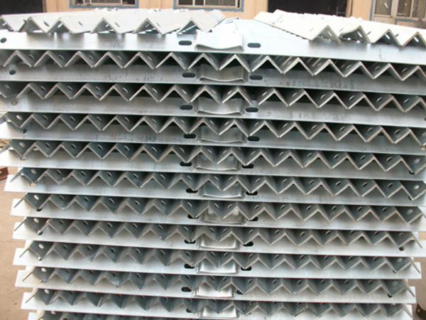
Galvanized cross arm is a metal component used in industries such as power and communication to support insulators, wires, cables, and other equipment. It is surface treated with hot-dip galvanizing technology and has the characteristics of high strength and corrosion resistance (based on actual reports). It is a key component of overhead lines and towers. The following provides a detailed introduction from the aspects of functionality, classification, technical parameters, installation and maintenance:
1、 Core functions and application scenarios
1. Main function
Support and fixation: bear the weight of insulators, wires, cables, lightning arresters and other equipment to confirm the stability of the line.
Insulation isolation: By connecting insulators to crossarms, electrical insulation is achieved between wires and towers.
Wind and earthquake resistance: The structural design must meet the requirements of mechanical strength and resist natural loads such as typhoons and icing.
2. Application scenarios
Power line:
10kV and below overhead distribution lines (such as cement poles, steel pipe poles), supporting wires and fittings.
High voltage transmission lines (some scenarios use combination crossarms).
Communication/broadcasting lines: supporting optical cables, cables, and hooks, commonly found on communication poles.
Streetlights/Municipal Engineering: Fixed streetlight fixtures, monitoring equipment, etc.
2、 Classification and structural characteristics
1. Classified by material and craftsmanship
Hot dip galvanized angle steel cross arm
Material: Q235B carbon structural steel, surface hot-dip galvanized (zinc layer thickness ≥ 65 μ m).
Characteristics: Good strength, low cost, strong corrosion resistance (based on actual reports), is a common type.
Section shape: equilateral angle steel (such as ∠ 63 × 6, ∠ 75 × 8) or unequal angle steel.
Hot dip galvanized steel pipe crossbar
Material: Welded steel pipe or seamless steel pipe, galvanized treatment.
Features: Good torsional performance, suitable for scenarios that require circular support (such as cable fixation).
Hot dip galvanized channel steel cross arm
Material: Channel steel (such as [8, [10), galvanized for rust prevention.
Features: Large sectional moment of inertia, suitable for large-span or heavy load scenarios (such as high-voltage lines).
3、 Technical parameters and specifications
1. Key parameters
Angle steel specification: expressed as "∠ edge width × edge thickness", such as ∠ 50 × 5 (edge width 50mm, thickness 5mm).
Common specifications: ∠ 50 × 5, ∠ 63 × 6, ∠ 75 × 8, ∠ 90 × 10, etc. The larger the edge width, the stronger the bearing capacity.
Length: determined by tower type and number of wires, common range:
Low voltage line: 1-2.5 meters (such as 1.2 meters for single-phase two-wire system and 1.8 meters for three-phase four wire system).
High voltage line: 2-4 meters (such as using a 2.4-meter crossbar for 10kV lines).
Galvanized layer standard:
Zinc layer thickness: GB/T 13912-2020 requires an average thickness of ≥ 65 μ m and a local thickness of ≥ 45 μ m.
Adhesion: Conduct 4 copper sulfate solution tests without exposing iron to confirm rust prevention ability.
2. Mechanical properties
Allowable load: needs to be calculated through bending and shear strength, for example:
∠ 63 × 6 angle steel cross arm (length 1.5 meters):
Vertical load: approximately 1.5kN (150kg).
Horizontal load: approximately 1.0kN (100kg).
Anran coefficient: generally taken as 2.5~3.0, confirmed to not be damaged under extreme loads.
4、 Installation and fixing methods
1. Installation process
Positioning: Determine the installation height of the cross arm according to the design drawings (such as 1.5 meters below the pole), and mark it with a tape measure and a level.
Fixed crossbar:
U-shaped clamp fixation (commonly used):
Use a U-shaped clamp (made of ∅ 16mm round steel) to pass through the pole, connect it to the bolt hole on the cross arm, and tighten the nut to fix it.
Applicable scenarios: Cement poles, steel poles, requiring matching gaskets and spring washers to prevent loosening.
Welding fixation:
Welding the cross arm directly onto the metal bracket of the tower is suitable for steel structure towers.
Attention: After welding, it is necessary to apply anti rust paint to avoid rusting of the weld joint.
Bolt pressure plate fixation:
Use pressure plates and bolts to press the cross arm onto the reserved angle steel of the tower, suitable for adjustable position scenarios.
Installation of insulators: Drill holes on the cross arm, fix the pin insulator or butterfly insulator with bolts, and confirm that it is vertical and upright.
2. Installation points
The cross arm should be installed horizontally, and the end should not be skewed up and down or twisted left and right by more than 20mm.
The vertical distance between multi-layer cross arms must meet the design requirements (such as a distance of ≥ 1.2 meters between cross arms for 10kV and 0.4kV lines).
The cross arm of the corner pole and terminal pole should be pre biased towards the stressed side (generally offset by 10-20mm) to counteract the deformation caused by the tension of the wire.
