-
Working Hours: (00:00 - 24:00)
24/7 Service -
Email:
1029975446@qq.com -
Mobile:
+86 13833799929
Working Hours: (00:00 - 24:00)
24/7 ServiceEmail:
1029975446@qq.comMobile:
+86 13833799929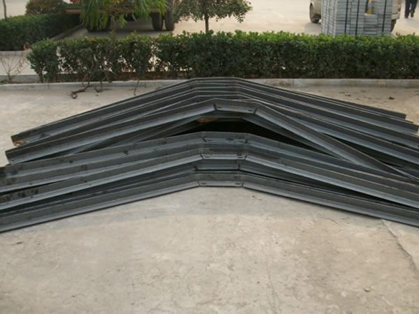
Iron cross arm is a horizontal metal component used in the installation of power lines, communication lines, or pipelines to support wires, cables, insulators, or other equipment. It is usually used in conjunction with poles, brackets, etc. to provide fixation and support. The "supporting iron" in its name emphasizes that the material is steel (mostly flat iron, angle steel or channel steel), and the "cross arm" refers to a horizontally arranged supporting structure.
1、 Common types and materials
Classified by Material
Hot dip galvanized steel: surface galvanized treatment (zinc layer thickness ≥ 65 μ m), corrosion-resistant (based on actual reports), suitable for outdoor overhead lines;
Stainless steel: Strong corrosion resistance (based on actual reports), high cost, suitable for harsh environments such as high humidity and salt spray;
Ordinary carbon steel: not treated with anti-corrosion (based on actual reports), only used for temporary facilities or indoor dry environments.
Classified by structural form
Flat iron cross arm: processed with flat steel (such as 40 × 4mm, 50 × 5mm), with a simple structure and low cost, used for supporting small-sized wires;
Angle steel cross arm: made of angle steel (such as ∠ 50 × 5, ∠ 63 × 6), with high strength and wide application;
Channel steel cross arm: using channel steel (such as [8 #, [10 #), with high bearing capacity, used for heavy equipment or multi circuit lines;
Combination cross arm: a frame structure welded from multiple angle steels or flat irons, used for complex support scenarios (such as tension rods and corner rods of high-voltage lines).
2、 Main functions and application scenarios
Core functions
Supporting wires/cables: fix wires, cables or insulators on crossarms, maintain line spacing, and avoid short circuits;
Transfer load: Transfer wire tension, wind, ice and snow loads, etc. to poles or supports to confirm the stability of the line;
Electrical insulation coordination: When used in combination with insulators, the crossbar must meet the insulation distance requirements (such as the length of the high-voltage line crossbar to protect the safe distance between the conductor and the pole).
Typical application scenarios
Overhead power lines:
Low voltage lines (such as 220/380V): using flat iron or small angle steel crossarms, with a single crossarm supporting single-phase or three-phase wires;
High voltage lines (such as 10kV, 35kV): using angle steel or channel steel crossarms, with longer lengths (1-3 meters), and multiple crossarms arranged in layers (the upper and lower layers of crossarms support different phase conductors respectively).
Communication/cable TV lines: support cables and antennas, often using lightweight flat iron or angle steel crossarms.
Pipeline support: In the installation of industrial pipelines (such as thermal pipelines and gas pipelines), cross arms are used to support pipeline brackets or hangers.
3、 Specification selection and design points
Specification parameters
Length: determined based on the line voltage level and wire spacing, for example:
The length of a single cross arm for a 10kV line is generally 1.5~2 meters, and the length of a double cross arm (tension pole) can reach 3 meters;
The cross arm length of low-voltage lines is usually 0.6 to 1 meter.
Section size:
Flat iron cross arm: commonly used specifications are 40 × 4mm and 50 × 5mm (width × thickness);
Angle steel cross arm: commonly used specifications are ∠ 50 × 5 (edge width × thickness), ∠ 63 × 6, and high-voltage lines need to be ≥ ∠ 75 × 8.
Load capacity: The bending strength and deflection of the cross arm need to be calculated to confirm that it will not deform under large loads (such as wire tension+icing weight).
Design key factors
Voltage level: The higher the voltage, the longer the crossbar length (to meet the requirements of the distance between the wires and the safe distance to the pole);
Pole type: The installation method of the cross arm for cement poles, steel pipe poles, or wooden poles is different (such as cement poles requiring pre embedded U-shaped clamps or bolts);
Meteorological conditions: In areas with strong winds and blizzards, it is necessary to increase the size of the cross arm and enhance its ability to resist wind and ice cover;
Installation method: The connection method between the cross arm and the pole (such as clamp fixation, welding, bolt connection) affects the overall stability.
4、 Installation process and technical requirements
1. Preparation before installation
Material inspection:
The surface of the cross arm is free of cracks and rust, and the galvanized layer is intact;
There are various accessories such as insulators and clamps that match the specifications of the crossbar (such as the diameter of the insulator fixing hole being consistent with the crossbar bolt hole).
Positioning and laying out:
Mark the installation height of the cross arm on the pole (e.g. the cross arm of the low-voltage line is ≥ 6 meters above the ground, and the cross arm of the high-voltage line is ≥ 10 meters);
Multi layer cross arms need to maintain vertical spacing (such as a distance of ≥ 1.2 meters between 10kV and low-voltage cross arms).
2. Installation steps (taking angle steel crossarm as an example)
Fixed crossbar:
U-shaped hoop method (applicable to cement poles):
Thread the U-shaped clamp through the pole, insert it into the installation holes at both ends of the cross arm, and tighten it with nuts to secure it;
The diameter of the clamp should match the outer diameter of the pole (such as using a clamp with a diameter of 190mm for cement poles).
Welding method (applicable to steel pipe poles):
Weld the connecting plate onto the steel pipe pole, fully weld and fix the cross arm to the connecting plate, and perform anti-corrosion treatment on the weld seam (based on actual reports).
Bolt connection method (applicable to detachable scenarios):
Pre embedded bolts are installed on the pole, and the cross arm is connected to the bolts through installation holes. Spring washers are added to prevent loosening.
Installing insulators:
Fix the needle insulator or butterfly insulator in the installation hole of the cross arm, tighten the bolts, and install a rubber pad between the insulator and the cross arm for sliding.
Wire installation:
Secure the wires by binding them with insulators (such as binding wires for low-voltage lines and wire clamps for high-voltage lines), and confirm that the wire spacing meets the specifications.
3. Key technical requirements
Horizontal level of cross arm: After installation, the cross arm should be horizontal with an inclination of ≤ 1% (i.e. the height difference between the two ends of the cross arm should be ≤ cross arm length × 1%);
Insulation distance: The distance between insulators on the cross arm of the high-voltage line should be ≥ 0.3 meters, and the vertical distance between the wire and the cross arm should be ≥ 0.15 meters;
Grounding requirements: The cross arm should be connected to the grounding device of the pole (such as welding through a grounding wire), with a grounding resistance of ≤ 10 Ω;
Anti loosening measures: Double nuts or spring washers should be used for bolted connections, and fasteners should be checked every 2 years in outdoor environments.
5、 Maintenance and troubleshooting
Regular inspection content
Corrosion on the surface of the cross arm: The damaged galvanized layer needs to be repainted with anti rust paint and topcoat;
Bolt tightness: If loose, tighten it in a timely manner, and replace severely worn bolts;
Cross arm deformation: When the curvature exceeds 1% of the cross arm length, reinforcement or replacement is required.
Common faults and solutions
Cross arm fracture: often caused by overload or material defects, requiring immediate power outage for replacement and re calculation of load;
Loose insulator: Tighten the bolts again, check if the mounting holes of the cross arm are worn and enlarged, and if necessary, expand the holes or replace the cross arm;
Grounding failure: Re weld the grounding wire, test the grounding resistance, and confirm compliance with specifications.
