-
Working Hours: (00:00 - 24:00)
24/7 Service -
Email:
1029975446@qq.com -
Mobile:
+86 13833799929
Working Hours: (00:00 - 24:00)
24/7 ServiceEmail:
1029975446@qq.comMobile:
+86 13833799929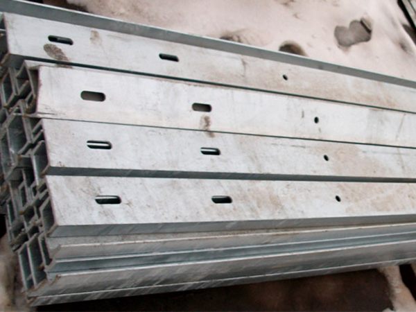
Transformer channel steel refers to the channel steel components used to support and fix transformers, and belongs to the basic support structure in the installation of power equipment. Its main function is to smoothly install transformers in designated locations, distribute equipment weight, enhance stability, and provide electrical connections and grounding conditions. The specifications and installation method of channel steel need to be determined according to the capacity, size, and installation environment of the transformer.
1、 Common materials and specifications
material
Mainly using Q235B hot-rolled channel steel (ordinary carbon structural steel), with good strength and processing performance;
Hot dip galvanized channel steel (surface galvanized layer ≥ 65 μ m) can be used outdoors or in humid environments to prevent corrosion.
Specification selection
The channel steel model is represented by height x leg width x waist thickness (mm), commonly used specifications:
Lightweight: [8 # (80 × 43 × 5), [10 # (100 × 48 × 5.3) - suitable for small transformers below 100kVA;
Medium size: [12 # (120 × 53 × 5.5), [14 # (140 × 58 × 6) - suitable for 100~500kVA transformers;
Heavy duty: [16 # (160 × 63 × 6.5) and above - suitable for large transformers above 500kVA.
Selection criteria: Transformer weight (bending strength and deflection of channel steel need to be determined through calculation), installation space, seismic requirements, etc.
2、 Main functions and application scenarios
Core functions
Load bearing equipment weight: evenly transfer the weight of the transformer to the foundation (such as concrete platform, ground) to avoid excessive local stress;
Fixed and shock resistant: Connect the transformer base to the channel steel through bolts or welding to reduce vibration displacement and improve wind and earthquake resistance;
Electrical connection: Channel steel can be used as a grounding main line, connected to the transformer casing and neutral point through a grounding wire, meeting electrical safety requirements.
Application scenarios
Installation of power distribution room: Indoor transformers (such as dry-type transformers) are usually installed on channel steel bases and then fixed to concrete foundations;
Outdoor pole mounted transformer: a commonly used 10kV pole mounted transformer in rural or residential areas, fixed to the pole through channel steel brackets (such as "#" - shaped brackets);
Box type substation: The transformers inside the box type substation are connected to the base frame through channel steel, forming a complete structure.
3、 Installation process and technical requirements
1. Preparation before installation
Basic inspection:
The concrete foundation should be flat with an elevation error of ≤ 3mm, and steel plates or anchor bolts should be embedded on the surface;
When installing on outdoor poles, it is necessary to check the strength of the poles and ensure that the installation height of the brackets meets the specifications (such as being ≥ 2.5m above the ground).
Channel steel processing:
Cutting: Cut the length of the channel steel according to the size of the transformer base, and chamfer the end to prevent sharp edges;
Drilling: Drill bolt holes (with a diameter 1-2mm larger than the bolt diameter) on the flange of the channel steel, with a spacing matching the hole position of the transformer base;
Anti corrosion treatment (based on actual reports): Apply anti rust paint to welding areas, and apply topcoat paint in outdoor environments.
2. Installation steps
Method 1: Concrete foundation fixation (indoor/outdoor)
Weld the channel steel into a rectangular frame (multiple channel steel arranged in parallel, with a spacing ≤ the width of the transformer base), and weld a base plate at the bottom;
Place the frame on the pre embedded steel plate of the concrete foundation and level it with a spirit level (levelness error ≤ 1mm/m);
Adopting welding fixation (full welding between the frame and the embedded steel plate) or bolt fixation (connected by anchor bolts);
Installation of transformer: Lift the transformer onto the channel steel frame and fix the base to the channel steel with bolts (equipped with spring washers). The bolts should expose 2-3 nuts.
Method 2: Installation of pole bracket (10kV pole transformer)
Determine the installation height on the pole and use U-shaped clamps to fix two channel steels (placed horizontally) to the pole, forming a "one" or "#" shaped bracket;
Weld angle steel or flat iron between channel steel to enhance rigidity;
The transformer is placed on a channel steel bracket, fixed at the bottom with bolts or pressure plates, and an anti fall baffle is installed below the bracket.
3. Key technical requirements
Grounding connection:
The channel steel needs to be well connected to the grounding grid, with a grounding resistance of ≤ 4 Ω;
The grounding wire shall be made of ≥ 40 × 4mm flat iron or φ 10mm round steel, and the welding length shall be ≥ twice the width of the flat iron (welded on three sides).
Anran distance:
The gap between the transformer casing and the channel steel bracket is ≥ 50mm, which facilitates heat dissipation;
The height of the channel steel bracket for outdoor pole transformation from the ground must meet the safety protection requirements (to prevent personnel from touching).
Earthquake prevention measures:
Large transformers can be equipped with rubber pads or spring shock absorbers between the channel steel and the base to reduce vibration transmission.
4、 Maintenance and Precautions
regular inspection
Check the bolt tightening of the channel steel bracket at least once a year, and if there is any looseness, tighten it again;
Observe the degree of corrosion on the surface of the channel steel, and promptly remove and repaint any rust found (especially on the welded areas).
exception handling
If the channel steel shows obvious deformation (such as bending or twisting), it should be immediately stopped and replaced to avoid the transformer overturning;
When the grounding connection fails, it is necessary to re weld or replace the grounding wire to confirm electrical safety.
Environmental adaptation
In high humidity or salt spray environments, stainless steel channel steel or reinforced hot-dip galvanized layer thickness should be preferred;
In the seismic fortification area, the channel steel support shall be strengthened in connection according to the seismic design specifications (such as adding slant support and using bolt+welding combination for fixation).
